本渲染器已完全重构,与之前版本大不相同,详情移步至TinySoftRenderer

  • 进入三维世界
  • 裁剪、剔除优化
  • 透视纹理映射、采样
  • 程序结果

一、进入三维世界

  尽管二维的屏幕只能显示二维的像素,但是我们可以通过将三维的物体变换到二维的屏幕上,从而渲染出三维空间的一个投影面。这与我们人类的视觉系统类似,视网膜上最终获取的也只是三维空间某个角度下的投影。为了让三维物体正确地显示到屏幕上,我们需要借助一系列的坐标空间变换。

1、坐标系统

  在渲染管线中,三维物体的顶点在最终转换为屏幕坐标之前会被变换到多个坐标系统,这其中有几个过渡性的坐标系,使得整个变换流程逻辑清晰、便于理解。此外在某些特定情况下在这些特定的坐标系中,一些操作更加容易、方便和灵活。通常,渲染管线有$5$个不同的坐标系统,分别是局部空间、世界空间、视觉空间、裁剪空间和屏幕空间,以下是LearnOpenGL CN)的原话:

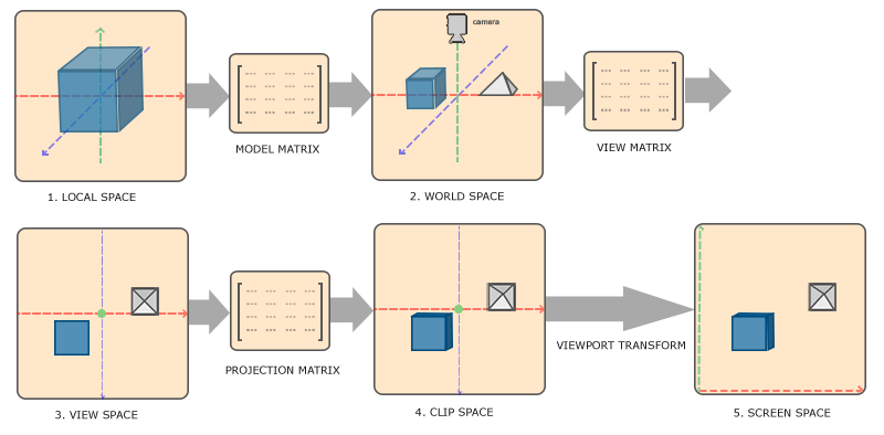
  1. 局部坐标是对象相对于局部原点的坐标,也是物体起始的坐标。

  2. 下一步是将局部坐标变换为世界空间坐标,世界空间坐标是处于一个更大的空间范围的。这些坐标相对于世界的全局原点,它们会和其它物体一起相对于世界的原点进行摆放。

  3. 接下来我们将世界坐标变换为观察空间坐标,使得每个坐标都是从摄像机或者说观察者的角度进行观察的。

  4. 坐标到达观察空间之后,我们需要将其投影到裁剪坐标。裁剪坐标会被处理至-1.0到1.0的范围内,并判断哪些顶点将会出现在屏幕上。

  5. 最后,我们将裁剪坐标变换为屏幕坐标,我们将使用一个叫做视口变换(Viewport Transform)的过程。视口变换将位于-1.0到1.0范围的坐标变换到由glViewport函数所定义的坐标范围内。最后变换出来的坐标将会送到光栅器,将其转化为片段

  通过以上的几个步骤,三维的物体坐标最终变换到了屏幕的坐标上,其中视图矩阵和投影矩阵的构建较为复杂一点,前面我的博文软渲染器Soft Renderer:3D数学篇已经推导过这两个矩阵,这里就不再赘述了。若想查看更多关于坐标系统的内容,请查看LearnOpenGL CN的这篇文章:坐标系统)。坐标变换是一般发生在顶点着色器以及顶点着色器输出到光栅化这一阶段,视口变换在顶点着色器输出之后,不在着色器中进行(视口变换已经在前面的光栅化篇提到过了)。所以为了实现坐标变换,我们的着色器要存储$model$、$view$、$project$这三个矩阵,在$SimpleShader$中添加相关的成员变量及方法:

1
2
3
4
5
6
7
8
9
10
11
12
13
14
15
16
17
18
19
20
21
22
23
24
25
26
27
28
29
class SimpleShader : public BaseShader
{
private:
Matrix4x4 m_modelMatrix;
Matrix4x4 m_viewMatrix;
Matrix4x4 m_projectMatrix;

public:
......

virtual void setModelMatrix(const Matrix4x4 &world);
virtual void setViewMatrix(const Matrix4x4 &view);
virtual void setProjectMatrix(const Matrix4x4 &project);
};

void SimpleShader::setModelMatrix(const Matrix4x4 &world)
{
m_modelMatrix = world;
}

void SimpleShader::setViewMatrix(const Matrix4x4 &view)
{
m_viewMatrix = view;
}

void SimpleShader::setProjectMatrix(const Matrix4x4 &project)
{
m_projectMatrix = project;
}

  这样外部要渲染时,应该向着色器输入这三个矩阵。然后在我们的顶点着色器中填入相关的逻辑:

1
2
3
4
5
6
7
8
9
10
VertexOut SimpleShader::vertexShader(const Vertex &in)
{
VertexOut result;
result.posTrans = m_modelMatrix * in.position;
result.posH = m_projectMatrix * m_viewMatrix * result.posTrans;
result.color = in.color;
result.normal = in.normal;
result.texcoord = in.texcoord;
return result;
}

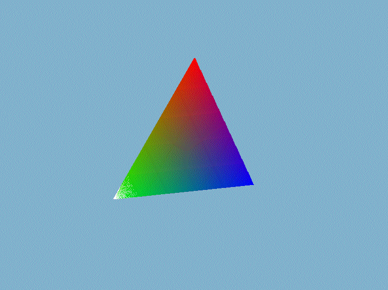
  $VertexOut$是前面文章定义的顶点着色器输出的类,它存储投影后的顶点$posH$、世界空间中的顶点$posTrans$、物体的颜色、顶点法线以及纹理坐标。接着在视口变换并送入光栅化部件之前执行透视除法,即直接将裁剪空间的顶点坐标除以它的第四个分量$w$即可。然后我们在外部的渲染循环中设置模型矩阵、视图矩阵已经投影矩阵,就能显示出三维的立体感了,以我们前一章画的三角形为例(gif录制的好像有bug,出现绿色它就给我录制成这个模糊的鬼样,实际上是非常清晰,不是渲染的锅)。

  进入3D世界,怎么能少了3D渲染的”hello world!”——立方体呢?在$Mesh.h$手动创建一个立方体的网格数据,然后用立方体替换掉上面丑陋的三角形:

1
2
3
4
5
6
7
8
9
10
11
12
13
14
15
16
17
18
19
20
21
22
23
24
25
26
27
28
29
30
31
32
33
34
35
36
37
38
39
40
41
42
43
44
45
46
47
48
49
50
51
52
53
54
55
56
57
58
59
60
61
62
63
64
65
66
67
68
69
70
71
72
73
74
75
76
77
78
79
80
81
82
83
84
85
86
87
88
89
90
91
92
93
94
95
96
97
98
99
100
101
102
103
104
105
106
107
108
109
110
111
112
113
114
115
116
117
118
119
120
121
122
123
124
125
126
127
128
129
130
131
132
133
134
135
136
137
138
139
140
141
142
143
144
145
146
147
148
149
150
151
152
153
154
void Mesh::asBox(double width, double height, double depth)
{
vertices.resize(24);
indices.resize(36);

float halfW = width * 0.5f;
float halfH = height * 0.5f;
float halfD = depth * 0.5f;
//front
vertices[0].position = Vector3D(halfW, halfH, halfD);
vertices[0].normal = Vector3D(0.f, 0.f, 1.f);
vertices[0].color = Vector4D(1.f, 0.f, 0.f, 1.f);
vertices[0].texcoord = Vector2D(1.f, 1.f);
vertices[1].position = Vector3D(-halfW, halfH, halfD);
vertices[1].normal = Vector3D(0.f, 0.f, 1.f);
vertices[1].color = Vector4D(0.f, 1.f, 0.f, 1.f);
vertices[1].texcoord = Vector2D(0.f, 1.f);
vertices[2].position = Vector3D(-halfW,-halfH, halfD);
vertices[2].normal = Vector3D(0.f, 0.f, 1.f);
vertices[2].color = Vector4D(0.f, 0.f, 1.f, 1.f);
vertices[2].texcoord = Vector2D(0.f, 0.f);
vertices[3].position = Vector3D(halfW, -halfH, halfD);
vertices[3].normal = Vector3D(0.f, 0.f, 1.f);
vertices[3].color = Vector4D(0.f, 1.f, 1.f, 1.f);
vertices[3].texcoord = Vector2D(1.f, 0.f);
//left
vertices[4].position = Vector3D(-halfW, +halfH, halfD);
vertices[4].normal = Vector3D(-1.f, 0.f, 0.f);
vertices[4].color = Vector4D(0.f, 0.f, 1.f, 1.f);
vertices[4].texcoord = Vector2D(1.f, 1.f);
vertices[5].position = Vector3D(-halfW, +halfH, -halfD);
vertices[5].normal = Vector3D(-1.f, 0.f, 0.f);
vertices[5].color = Vector4D(1.f, 1.f, 0.f, 1.f);
vertices[5].texcoord = Vector2D(0.f, 1.f);
vertices[6].position = Vector3D(-halfW, -halfH, -halfD);
vertices[6].normal = Vector3D(-1.f, 0.f, 0.f);
vertices[6].color = Vector4D(0.f, 1.f, 0.f, 1.f);
vertices[6].texcoord = Vector2D(0.f, 0.f);
vertices[7].position = Vector3D(-halfW, -halfH, halfD);
vertices[7].normal = Vector3D(-1.f, 0.f, 0.f);
vertices[7].color = Vector4D(1.f, 1.f, 1.f, 1.f);
vertices[7].texcoord = Vector2D(1.f, 0.f);
//back
vertices[8].position = Vector3D(-halfW, +halfH, -halfD);
vertices[8].normal = Vector3D(0.f, 0.f, -1.f);
vertices[8].color = Vector4D(1.f, 0.f, 1.f, 1.f);
vertices[8].texcoord = Vector2D(0.f, 0.f);
vertices[9].position = Vector3D(+halfW, +halfH, -halfD);
vertices[9].normal = Vector3D(0.f, 0.f, -1.f);
vertices[9].color = Vector4D(0.f, 1.f, 1.f, 1.f);
vertices[9].texcoord = Vector2D(1.f, 0.f);
vertices[10].position = Vector3D(+halfW, -halfH, -halfD);
vertices[10].normal = Vector3D(0.f, 0.f, -1.f);
vertices[10].color = Vector4D(1.f, 1.f, 0.f, 1.f);
vertices[10].texcoord = Vector2D(1.f, 1.f);
vertices[11].position = Vector3D(-halfW, -halfH, -halfD);
vertices[11].normal = Vector3D(0.f, 0.f, -1.f);
vertices[11].color = Vector4D(0.f, 0.f, 1.f, 1.f);
vertices[11].texcoord = Vector2D(0.f, 1.f);
//right
vertices[12].position = Vector3D(halfW, +halfH, -halfD);
vertices[12].normal = Vector3D(1.f, 0.f, 0.f);
vertices[12].color = Vector4D(0.f, 1.f, 0.f, 1.f);
vertices[12].texcoord = Vector2D(0.f, 0.f);
vertices[13].position = Vector3D(halfW, +halfH, +halfD);
vertices[13].normal = Vector3D(1.f, 0.f, 0.f);
vertices[13].color = Vector4D(1.f, 0.f, 0.f, 1.f);
vertices[13].texcoord = Vector2D(1.f, 0.f);
vertices[14].position = Vector3D(halfW, -halfH, +halfD);
vertices[14].normal = Vector3D(1.f, 0.f, 0.f);
vertices[14].color = Vector4D(0.f, 1.f, 1.f, 1.f);
vertices[14].texcoord = Vector2D(1.f, 1.f);
vertices[15].position = Vector3D(halfW, -halfH, -halfD);
vertices[15].normal = Vector3D(1.f, 0.f, 0.f);
vertices[15].color = Vector4D(1.f, 0.f, 1.f, 1.f);
vertices[15].texcoord = Vector2D(0.f, 1.f);
//top
vertices[16].position = Vector3D(+halfW, halfH, -halfD);
vertices[16].normal = Vector3D(0.f, 1.f, 0.f);
vertices[16].color = Vector4D(0.f, 0.f, 0.f, 1.f);
vertices[16].texcoord = Vector2D(0.f, 0.f);
vertices[17].position = Vector3D(-halfW, halfH, -halfD);
vertices[17].normal = Vector3D(0.f, 1.f, 0.f);
vertices[17].color = Vector4D(1.f, 1.f, 0.f, 1.f);
vertices[17].texcoord = Vector2D(1.f, 0.f);
vertices[18].position = Vector3D(-halfW, halfH, halfD);
vertices[18].normal = Vector3D(0.f, 1.f, 0.f);
vertices[18].color = Vector4D(0.f, 1.f, 1.f, 1.f);
vertices[18].texcoord = Vector2D(1.f, 1.f);
vertices[19].position = Vector3D(+halfW, halfH, halfD);
vertices[19].normal = Vector3D(0.f, 1.f, 0.f);
vertices[19].color = Vector4D(1.f, 0.f, 0.f, 1.f);
vertices[19].texcoord = Vector2D(0.f, 1.f);
//down
vertices[20].position = Vector3D(+halfW, -halfH, -halfD);
vertices[20].normal = Vector3D(0.f, -1.f, 0.f);
vertices[20].color = Vector4D(0.f, 0.f, 1.f, 1.f);
vertices[20].texcoord = Vector2D(0.f, 0.f);
vertices[21].position = Vector3D(+halfW, -halfH, +halfD);
vertices[21].normal = Vector3D(0.f, -1.f, 0.f);
vertices[21].color = Vector4D(1.f, 1.f, 1.f, 1.f);
vertices[21].texcoord = Vector2D(1.f, 0.f);
vertices[22].position = Vector3D(-halfW, -halfH, +halfD);
vertices[22].normal = Vector3D(0.f, -1.f, 0.f);
vertices[22].color = Vector4D(0.f, 1.f, 0.f, 1.f);
vertices[22].texcoord = Vector2D(1.f, 1.f);
vertices[23].position = Vector3D(-halfW, -halfH, -halfD);
vertices[23].normal = Vector3D(0.f, -1.f, 0.f);
vertices[23].color = Vector4D(1.f, 0.f, 1.f, 1.f);
vertices[23].texcoord = Vector2D(0.f, 1.f);

//front
indices[0] = 0;
indices[1] = 1;
indices[2] = 2;
indices[3] = 0;
indices[4] = 2;
indices[5] = 3;
//left
indices[6] = 4;
indices[7] = 5;
indices[8] = 6;
indices[9] = 4;
indices[10] = 6;
indices[11] = 7;
//back
indices[12] = 8;
indices[13] = 9;
indices[14] = 10;
indices[15] = 8;
indices[16] = 10;
indices[17] = 11;
//right
indices[18] = 12;
indices[19] = 13;
indices[20] = 14;
indices[21] = 12;
indices[22] = 14;
indices[23] = 15;
//top
indices[24] = 16;
indices[25] = 17;
indices[26] = 18;
indices[27] = 16;
indices[28] = 18;
indices[29] = 19;
//down
indices[30] = 20;
indices[31] = 21;
indices[32] = 22;
indices[33] = 20;
indices[34] = 22;
indices[35] = 23;
}

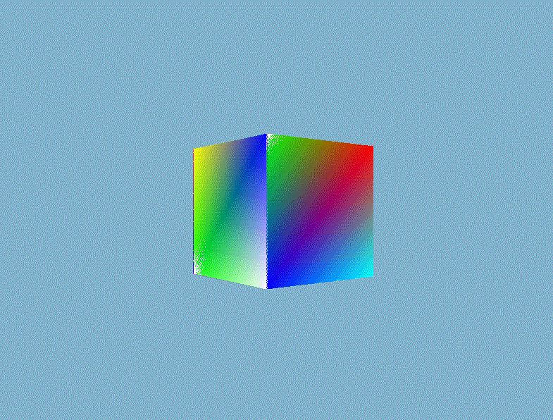
  结果我们就得到一个如下面所示的奇怪的立方体:

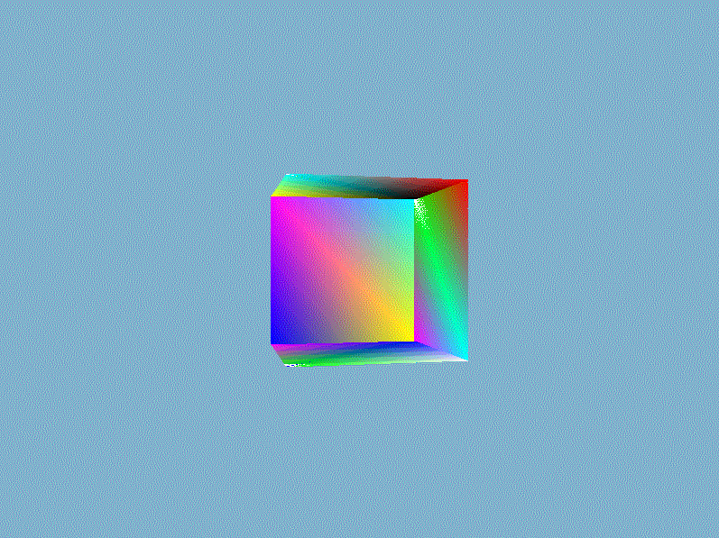
  这的确有点像是一个立方体,但又有种说不出的奇怪。立方体的某些本应被遮挡住的面被绘制在了这个立方体其他面之上。出现这样结果的原因是因为我们的软渲染器是对一个一个三角形进行绘制的,而且计算像素时时直接覆盖而不管这个像素是否已经有其他值了,所以一个像素的值完全取决于最后赋予它的$RGBA$。除非渲染管线自动按照从远到近的顺序(这类算法有画家算法、空间分割BSP树算法)绘制三角形,否则直接覆盖的方法获取不了正确的像素值。正确渲染结果应该是像素的$RGBA$值为最靠近视点的片元值,一种常用的技术是借助第三维信息——深度来对每个相同位置的不同片元做深度的比较,并且取深度较低的那一个。

2、深度测试

  为了获取正确的三维渲染结果,我们采用一种深度缓冲的技术。深度缓冲存储深度信息,它的分辨率应该与颜色缓冲一致,深度值存储在每个片段里面(作为片段的z值),当片段想要输出它的颜色时,我们将它的深度值和z缓冲进行比较,如果当前的片段在其它片段之后,它将会被丢弃,否则将会覆盖。这个过程称为深度测试。在OpenGL和DirectX这些渲染API中,深度缓冲会自动执行而无需用户操作。在我们的软渲染器中,我们自己实现一个这样的深度测试,算法原理很简单,但是效果非常不错!

  深度缓冲通常和颜色缓冲一起,作为帧缓冲的附件,我们在帧缓冲类中增加深度缓冲相关的变量、方法:

1
2
3
4
5
6
7
8
9
10
11
12
13
14
15
16
17
18
19
20
21
22
23
24
25
26
27
28
29
30
31
32
33
34
35
36
37
38
39
40
41
42
43
44
45
46
47
48
49
50
class FrameBuffer
{
private:
......
std::vector<double> m_depthBuffer;

public:

......

void clearColorAndDepthBuffer(const Vector4D &color);

double getDepth(const unsigned int &x, const unsigned int &y)const;

void drawDepth(const unsigned int &x, const unsigned int &y, const double &value);

};

void FrameBuffer::clearColorAndDepthBuffer(const Vector4D &color)
{
// fill the color buffer and depth buffer.
unsigned char red = static_cast<unsigned char>(255*color.x);
unsigned char green = static_cast<unsigned char>(255*color.y);
unsigned char blue = static_cast<unsigned char>(255*color.z);
unsigned char alpha = static_cast<unsigned char>(255*color.w);

for(unsigned int row = 0;row < m_height;++ row)
{
for(unsigned int col = 0;col < m_width;++ col)
{
m_depthBuffer[row*m_width+col] = 1.0f;
......
}
}
}

double FrameBuffer::getDepth(const unsigned int &x, const unsigned int &y) const
{
if(x < 0 || x >= m_width || y < 0 || y >= m_height)
return 0.0f;
return m_depthBuffer[y*m_width+x];
}

void FrameBuffer::drawDepth(const unsigned int &x, const unsigned int &y, const double &value)
{
if(x < 0 || x >= m_width || y < 0 || y >= m_height)
return;
unsigned int index = y*m_width + x;
m_depthBuffer[index] = value;
}

  然后我们对于每一个片元,我们获取深度缓冲中相应的数值并进行比较。在这之前,我们还要简单回顾一下在透视投影矩阵中深度值的非线性映射,在前面的数学篇中我们知道透视投影矩阵有如下形式:

  因而视图空间中的深度信息$z_e$和标准化设备空间中的深度信息$z_n$关系为:

  可以看到$z_e$d到$z_n$是一种从$[-f, -n]$到$[-1,1]$的非线性映射。当$z_e$比较小的时候,公式$(1)$有很高的精度;当$z_e$比较大的时候,公式$(1)$应为取值精度降低。这个关系可以直观地从下图的函数曲线看出来:

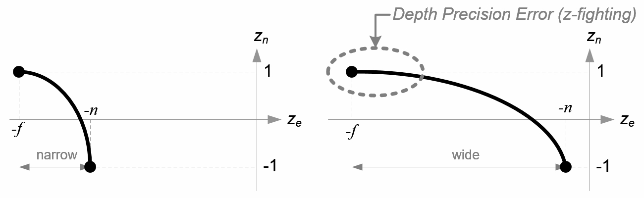
  可以看到,深度值很大一部分是由很小的z值所决定的,这给了近处的物体很大的深度精度。$z_n$取值为$[-1,1]$,我们最后将其简单地映射到$[0,1]$,这一步我放在透视除法后。

1
2
3
4
5
6
7
8
9
void Pipeline::perspectiveDivision(VertexOut &target)
{
target.posH.x /= target.posH.w;
target.posH.y /= target.posH.w;
target.posH.z /= target.posH.w;
target.posH.w = 1.0f;
// map from [-1,1] to [0,1]
target.posH.z = (target.posH.z+1.0f) * 0.5f;
}

  在写入深度缓冲之前应该要清除上一帧的深度缓冲,全部置$1.0f$即可,我把这一步和清除颜色缓冲放一起了,即前面的帧缓冲类的$clearColorAndDepthBuffer$方法。在光栅化步骤,获取每个片元的屏幕位置,查找深度缓并比较,若小于当前深度缓冲中获取的值,则通过深度测试并写入深度缓冲。

1
2
3
4
5
6
7
8
9
10
11
12
13
14
15
16
17
18
19
20
21
22
23
24
25
26
27
28
void Pipeline::scanLinePerRow(const VertexOut &left, const VertexOut &right)
{
// scan the line from left to right.
VertexOut current;
int length = right.posH.x - left.posH.x + 1;
for(int i = 0;i <= length;++i)
{
// linear interpolation
double weight = static_cast<double>(i)/length;
current = lerp(left, right, weight);
current.posH.x = left.posH.x + i;
current.posH.y = left.posH.y;

// depth testing.
double depth = m_backBuffer->getDepth(current.posH.x, current.posH.y);
if(current.posH.z > depth)
continue;// fail to pass the depth testing.
m_backBuffer->drawDepth(current.posH.x,current.posH.y,current.posH.z);

double w = 1.0/current.oneDivZ;
current.posTrans *= w;
current.color *= w;
current.texcoord *= w;
// fragment shader
m_backBuffer->drawPixel(current.posH.x, current.posH.y,
m_shader->fragmentShader(current));
}
}

  然后就可以根据深度信息正确地渲染出三维的立体感了。

3、裁剪、剔除优化

  目前目前我们已经构建出三维的渲染管线,但是这还不够,因为图形渲染计算量很大,通常我们需要做一些优化。常见的嵌入在渲染管线中的优化算法有几何裁剪、背面剔除。

几何裁剪

  注意在坐标系统的变换过程中,位于视锥体内的顶点坐标各分量都会被映射到$[-1,1]$的范围内,超出视锥体的顶点则被映射到超出$[-1,1]$的范围。我们在这个基础上的做相关的裁剪,注意在透视除法之前各分量实际上是处于$[-w,w]$的范围内的,这里的$w$就是该顶点坐标的第四个分量$w$。针对线框模式渲染和填充模式渲染,我们有两种不同的裁剪算法。

Cohen-Sutherland线条裁剪算法

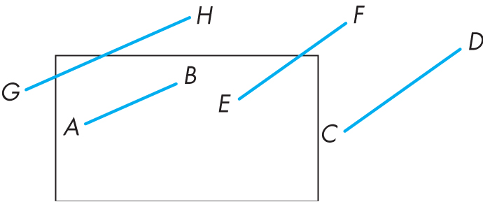
  一条线段在视口内的情况有如下所示的四种。其中端点完全在视口内和一端在视口内而另一端是在视口外的情况很好判断,但是线段完全在视口外就没那么简单了。可以看到线段$GH$的端点都在视口外部,但是线段的一部分却在视口的内部,这是如果直接根据两个端点是否在视口外做剔除的话会导致在边缘部分的线段直接消失,得到错误的结果。一种暴力的解法就是计算线段与视口窗口的交点,但是这并不高效。

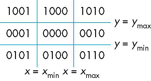
  Cohen-Sutherland提出了一种基于编码的判断算法,通过简单的移位、与或逻辑运算就可以判断一条线段处于哪种情况。对于每一个端点$(x,y)$,我们定义一个outcode——$b_0b_1b_2b_3$,视口所处的范围用$x_{min}$、$x_{max}$、$y_{min}$、$y_{max}$表示。每个端点$(x,y)$的outcode的计算方法如下:

  $b_0 = 1\ if \ y > y_{max},\ 0\ otherwiose$

  $b_1 = 1\ if \ y < y_{min},\ 0\ otherwiose$

  $b_2 = 1\ if \ x > x_{min},\ 0\ otherwiose$

  $b_3 = 1\ if \ x < x_{max},\ 0\ otherwiose$

  可以看出outcode将屏幕空间分成了$9$个部分:

  观察上面的$9$个区域,对于两个端点outcode1和outcode2,做如下的判断策略,其中的$OR$和$AND$是逻辑按位运算:

  若$(outcode1\ OR\ outcode2)==0$,那么线段就完全在视口内部;

  若$(outcode1\ AND\ outcode2)!=0$,那么线段就完全在视口外部;

  若$(outcode1\ AND\ outcode2)==0$,那么线段就可能部分在视口外部,部分在内部,还需要做进一步的判断(这里我进一步判断用了包围盒,因为比较常见和简单,就不过多描述了)。

  这里我的实现就是只裁剪掉肯定完全在视口外部的线段,若还想裁剪掉部分外视口外部的线段则需要进一步的求交运算。

1
2
3
4
5
6
7
8
9
10
11
12
13
14
15
16
17
18
19
20
21
22
23
24
25
26
27
28
29
30
31
32
33
34
35
36
37
38
39
40
41
42
43
44
45
46
47
48
49
50
bool Pipeline::lineCliping(const VertexOut &from, const VertexOut &to)
{
// return whether the line is totally outside or not.
float vMin = -from.posH.w, vMax = from.posH.w;
float x1 = from.posH.x, y1 = from.posH.y;
float x2 = to.posH.x, y2 = to.posH.y;

int tmp = 0;
int outcode1 = 0, outcode2 = 0;

// outcode1 calculation.
tmp = (y1>vMax)?1:0;
tmp <<= 3;
outcode1 |= tmp;
tmp = (y1<vMin)?1:0;
tmp <<= 2;
outcode1 |= tmp;
tmp = (x1>vMax)?1:0;
tmp <<= 1;
outcode1 |= tmp;
tmp = (x1<vMin)?1:0;
outcode1 |= tmp;

// outcode2 calculation.
tmp = (y2>vMax)?1:0;
tmp <<= 3;
outcode2 |= tmp;
tmp = (y2<vMin)?1:0;
tmp <<= 2;
outcode2 |= tmp;
tmp = (x2>vMax)?1:0;
tmp <<= 1;
outcode2 |= tmp;
tmp = (x2<vMin)?1:0;
outcode2 |= tmp;

if((outcode1 & outcode2) != 0)
return true;

// bounding box judge.
Vector2D minPoint,maxPoint;
minPoint.x = min(from.posH.x, to.posH.x);
minPoint.y = min(from.posH.y, to.posH.y);
maxPoint.x = max(from.posH.x, to.posH.x);
maxPoint.y = max(from.posH.y, to.posH.y);
if(minPoint.x > vMax || maxPoint.x < vMin || minPoint.y > vMax || maxPoint.y < vMin)
return true;

return false;
}

三角形裁剪

  齐次空间三角形精准裁剪见此链接

背面剔除

  背面剔除网上的这篇博客已经讲得非常详细了,原理也很简单,我就不过多描述。我们定义顶点逆时针的环绕顺序正面,然后通过三角形的三个顶点计算出法线,将顶点与视线做点乘并判断其符号即可。

1
2
3
4
5
6
7
8
9
10
11
12
13
14
15
bool Pipeline::backFaceCulling(const Vector4D &v1, const Vector4D &v2, const Vector4D &v3)
{
// back face culling.
if(m_mode == RenderMode::wire)
return true;
Vector4D tmp1 = v2 - v1;
Vector4D tmp2 = v3 - v1;
Vector3D edge1(tmp1.x, tmp1.y, tmp1.z);
Vector3D edge2(tmp2.x, tmp2.y, tmp2.z);
Vector3D viewRay(m_eyePos.x - v1.x,
m_eyePos.y - v1.y,
m_eyePos.z - v1.z);
Vector3D normal = edge1.crossProduct(edge2);
return normal.dotProduct(viewRay) > 0;
}

  然后背面剔除应该放在渲染管线的顶点着色器输出之后,如下所示:

1
2
3
4
5
6
7
8
9
10
11
12
13
14
15
16
17
18
19
20
21
22
23
24
25
26
27
28
29
30
31
32
33
34
35
36
37
38
39
40
41
42
43
44
45
46
47
48
49
void Pipeline::drawIndex(RenderMode mode)
{
// renderer pipeline.
bool line1 = false, line2 = false, line3 = false;
m_mode = mode;
if(m_indices.empty())return;

for(unsigned int i = 0;i < m_indices.size();i += 3)
{
//! assembly to triangle primitive.
Vertex p1,p2,p3;
{
......
}

//! vertex shader stage.
VertexOut v1,v2,v3;
{
......
}

//! back face culling.
{
if(!backFaceCulling(v1.posTrans, v2.posTrans, v3.posTrans))
continue;
}

//! geometry cliping.
{
......
}

//! perspective division.
{
......
}

//! view port transformation.
{
......
}


//! rasterization and fragment shader stage.
{
......
}
}
}

二、透视纹理映射、采样

  纹理映射是丰富三维物体细节的一个非常重要的方法,简单、廉价、快速,只需计算好的纹理坐标、纹理图片即可实现物体的多姿多彩。通常纹理图片的制作(除了过程式纹理的生成)由设计师完成,无需我们关心。而纹理坐标的计算则需要非常注意,送入渲染管线的纹理坐标只是逐顶点的纹理坐标,在光栅化阶段我们还要将纹理坐标做插值操作,最后根据插值后得到的纹理坐标对纹理图片采样获取片元的像素值。

1、透视纹理映射

  在光栅化阶段,我们是根据屏幕空间的$x$值和$y$值做线性插值操作获取片元的位置,而片元的纹理坐标如果也这么获得的话(这种方法叫做仿射纹理映射),将会导致严重的纹理扭曲。这是因为仿射纹理映射是基于这样的一个假设:物体空间的纹理坐标与屏幕空间的顶点坐标呈线性管线。

  我们知道纹理坐标是定义在物体的顶点上面的,当我们根据屏幕空间的顶点坐标插值时,就默认了纹理坐标的变化与屏幕空间顶点坐标的变化是呈线性、均匀的关系的。但是问题在于:默认的屏幕空间上的线性关系,还原到世界空间中,就不是那么回事了。除了纹理坐标,所有定义在世界空间线性关系下的属性插值都需要进行透视矫正,例如深度、法线向量、世界空间顶点坐标等等。

  关于透视矫正插值见此链接

2、双线性纹理采样

  定义的纹理坐标都是$[0.0f,1.0f]$的浮点数,为了采样纹理我们需要把它乘上纹理的宽高转成整数的下标取访问纹理的像素矩阵。乘上纹理的宽高之后我们得到的依然应该是一个浮点数,为了获取像素下标,一个简单的方法就是向下取整(这种采样方法对应于OpenGL的GL_NEAREST纹理过滤方法)。如下所示:

1
2
3
4
5
6
7
8
9
10
double trueU = texcoord.x * (m_width - 1);
double trueV = texcoord.y * (m_height - 1);
x = static_cast<unsigned int>(trueU);
y = static_cast<unsigned int>(trueV);
int index[0] = (x * m_width + y) * m_channel;
Vector3D texels;
// INV_SCALE is 1.0/255
texels.x = static_cast<float>(m_pixelBuffer[index + 0]) * INV_SCALE;
texels.y = static_cast<float>(m_pixelBuffer[index + 1]) * INV_SCALE;
texels.z = static_cast<float>(m_pixelBuffer[index + 2]) * INV_SCALE;

  问题就出在这里,这样直接抛弃小数点以后的值导致采样出的相邻纹理并不连续,那么用float采样行吗?答案是:不行!这边实现的采样函数是从数组取值,纹理坐标转为数组下标,数组下标不能用float只能用int,那么就没办法了吗?并不是,可以对周围纹理进行采样然后按照各自比例进行混合,这样能够提高显示效果。混合的方法就是双线性插值。所谓双线性插值,就是先后线性插值一次,共两次。即横向线性插值一次,然后根据前面一次的插值结果竖向插值一次,二维纹理是有两个维度,所以做双线性插值。

  除了采样之外,还有一个纹理坐标溢出的问题。纹理坐标超过的$[0,1]$通常由两种处理方式,一种是$clamp$,超过$[0,1]$的地方的像素都获取边上的像素,这样效果就是拉伸。一种是$repeat$,故名思议,即重复平铺。这里我实现的是重复平铺,在计算真正的纹理下标之前做相应的判断和处理即可。

1
2
3
4
5
6
7
8
9
10
11
12
13
14
15
16
17
18
19
20
21
22
23
24
25
26
27
28
29
30
31
32
33
34
35
36
37
38
39
40
41
42
43
44
45
46
47
48
49
50
51
52
53
54
55
56
57
58
59
60
61
62
63
64
65
66
67
68
69
70
71
72
73
74
75
76
77
78
79
80
81
82
83
84
85
86
87
88
89
90
91
92
93
94
95
96
97
98
99
100
101
102
103
104
105
106
107
108
class Texture2D
{
private:
int m_width;
int m_height;
int m_channel;
unsigned char *m_pixelBuffer;

public:
Texture2D():m_width(0), m_height(0), m_channel(0), m_pixelBuffer(nullptr){}
~Texture2D();

bool loadImage(const std::string &path);

Vector4D sample(const Vector2D &texcoord) const;

};

bool Texture2D::loadImage(const std::string &path)
{
if(m_pixelBuffer)delete m_pixelBuffer;
m_pixelBuffer = nullptr;
m_pixelBuffer = stbi_load(path.c_str(), &m_width, &m_height, &m_channel, 0);
if(m_pixelBuffer == nullptr)
{
qDebug() << "Failed to load image->" << QString::fromStdString(path);
}
return m_pixelBuffer != nullptr;
}

Vector4D Texture2D::sample(const Vector2D &texcoord) const
{
// just for rgb and rgba format.
Vector4D result(0.0,0.0,0.0,1.0);
if(m_pixelBuffer == nullptr)
return result;
unsigned int x = 0, y = 0;
// for bilinear interpolation.
double factorU = 0, factorV = 0;

// calculate the corresponding coordinate.
if(texcoord.x >= 0.0f && texcoord.x <= 1.0f && texcoord.y >= 0.0f && texcoord.y <= 1.0f)
{
double trueU = texcoord.x * (m_width - 1);
double trueV = texcoord.y * (m_height - 1);
x = static_cast<unsigned int>(trueU);
y = static_cast<unsigned int>(trueV);
factorU = trueU - x;
factorV = trueV - y;
}
else
{
// repeating way.
float u = texcoord.x,v = texcoord.y;
if(texcoord.x > 1.0f)
u = texcoord.x - static_cast<int>(texcoord.x);
else if(texcoord.x < 0.0f)
u = 1.0f - (static_cast<int>(texcoord.x) - texcoord.x);
if(texcoord.y > 1.0f)
v = texcoord.y - static_cast<int>(texcoord.y);
else if(texcoord.y < 0.0f)
v = 1.0f - (static_cast<int>(texcoord.y) - texcoord.y);

double trueU = u * (m_width - 1);
double trueV = v * (m_height - 1);
x = static_cast<unsigned int>(trueU);
y = static_cast<unsigned int>(trueV);
factorU = trueU - x;
factorV = trueV - y;
}
// texel fetching.
Vector3D texels[4];
int index[4];
index[0] = (x * m_width + y) * m_channel;
index[1] = (x * m_width + y + 1) * m_channel;
index[2] = ((x + 1) * m_width + y + 1) * m_channel;
index[3] = ((x + 1) * m_width + y) * m_channel;

// left bottom
texels[0].x = static_cast<float>(m_pixelBuffer[index[0] + 0]) * INV_SCALE;
texels[0].y = static_cast<float>(m_pixelBuffer[index[0] + 1]) * INV_SCALE;
texels[0].z = static_cast<float>(m_pixelBuffer[index[0] + 2]) * INV_SCALE;
//return texels[0];

// left top
texels[1].x = static_cast<float>(m_pixelBuffer[index[1] + 0]) * INV_SCALE;
texels[1].y = static_cast<float>(m_pixelBuffer[index[1] + 1]) * INV_SCALE;
texels[1].z = static_cast<float>(m_pixelBuffer[index[1] + 2]) * INV_SCALE;

// right top
texels[2].x = static_cast<float>(m_pixelBuffer[index[2] + 0]) * INV_SCALE;
texels[2].y = static_cast<float>(m_pixelBuffer[index[2] + 1]) * INV_SCALE;
texels[2].z = static_cast<float>(m_pixelBuffer[index[2] + 2]) * INV_SCALE;

// right bottom
texels[3].x = static_cast<float>(m_pixelBuffer[index[3] + 0]) * INV_SCALE;
texels[3].y = static_cast<float>(m_pixelBuffer[index[3] + 1]) * INV_SCALE;
texels[3].z = static_cast<float>(m_pixelBuffer[index[3] + 2]) * INV_SCALE;

// bilinear interpolation.
// horizational
texels[0] = texels[0] * (1.0 - factorU) + texels[3] * factorU;
texels[1] = texels[1] * (1.0 - factorU) + texels[2] * factorU;
//vertical
result = texels[0] * (1.0 - factorV) + texels[1] *factorV;

return result;
}

  加载图片我的用的stb_image,一个简单使用的头文件,因为加载图片不是我们的重点,所以就不造这方面的轮子了。
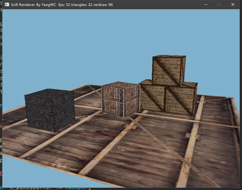
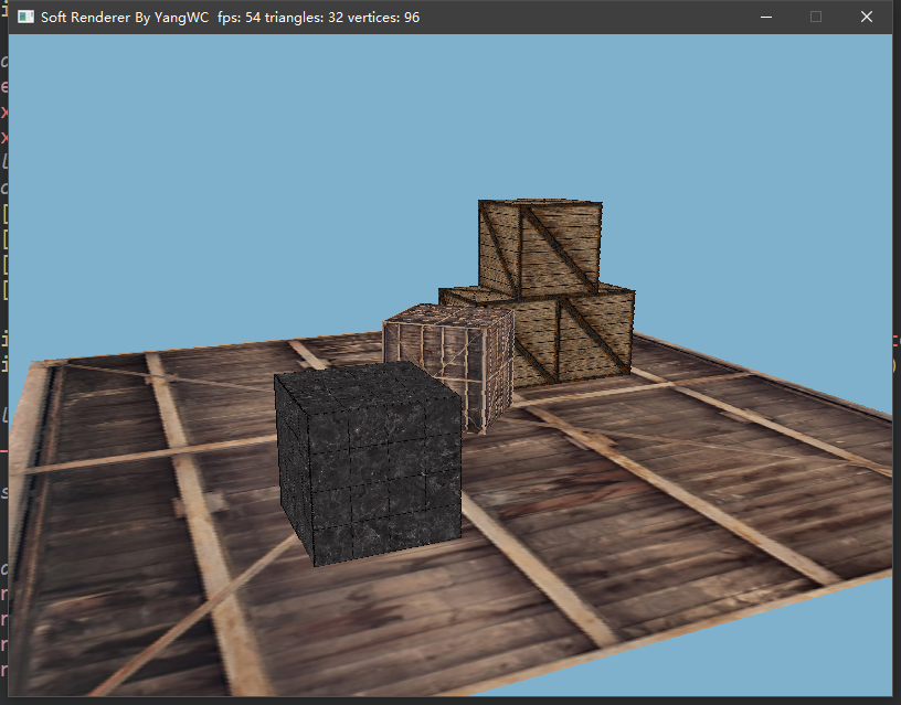
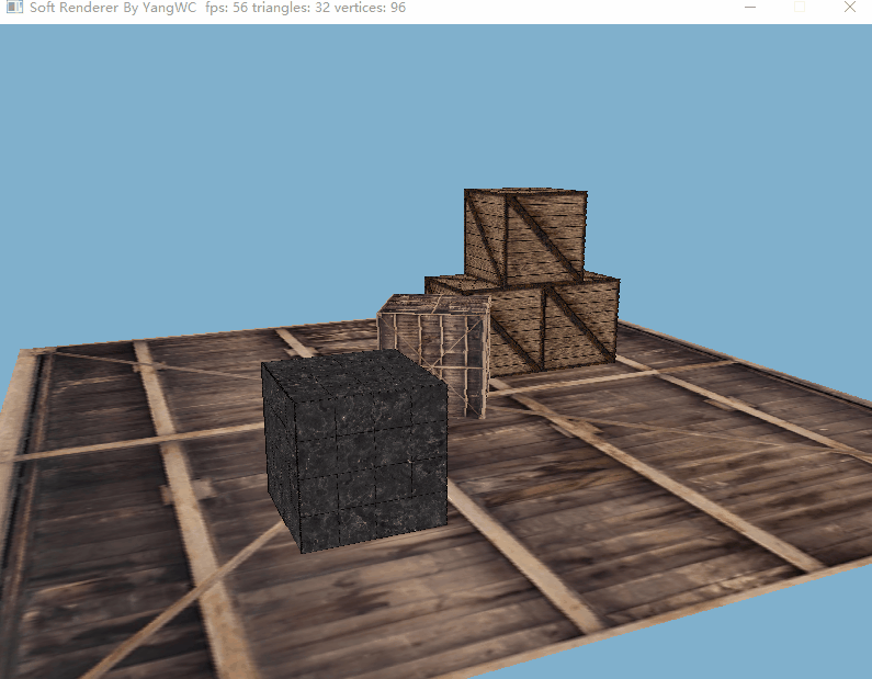
三、程序结果

  目前的帧率还不错hhh。

参考资料

$[1]$ https://learnopengl.com/Advanced-OpenGL/Depth-testing

$[2]$ https://www.cnblogs.com/pbblog/p/3484193.html

$[3]$ https://learnopengl.com/Getting-started/Coordinate-Systems

$[4]$ http://www.songho.ca/opengl/gl_projectionmatrix.html

$[5]$ https://blog.csdn.net/popy007/article/details/5570803

$[6]$ https://learnopengl-cn.github.io/01%20Getting%20started/06%20Textures/

 评论


博客内容遵循 署名-非商业性使用-相同方式共享 4.0 国际 (CC BY-NC-SA 4.0) 协议

本站使用 Material X 作为主题 , 总访问量为 次 。
载入天数...载入时分秒...